20 May Introduction to Line Impedance Stabilization Networks
Wayne Miller, General Manager of American Environments Company.
During the set-up phase of EMI test programs I usually get the question ‘What is the box you are installing on the ground plane?’ or ‘Are those filters?’ The device I am referring to is the Line Impedance Stabilization Network or LISN as it is more commonly known.
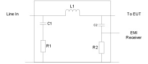
Figure 1 Typical LISN Block Diagram
The intent of the LISN is to create an artificial impedance to simulate a specific aircraft and its electrical systems. Over the years the LISN has evolved and it is primarily used to perform common mode conducted emissions measurements on input power leads.
The standardized line impedance (Typically 50 µH or 5µH) provided by the LISN is intended to ensure consistent between different test agencies.
The LISN also acts as specialized low pass filter. The filter is designed to prevent unwanted noise from coming in on the power leads and tainting the measurement EUT, likewise this will also prevent noise from the EUT from getting back onto the power mains.
The impedance versus frequency of an LISN must match the requirements of the test specification being applied. Typically this information will be in the test procedure or test standard being utilized. It is also important that the LISN can handle the input power requirements of the EUT. (Many LISNs cannot handle a 400 Hz input)
It is not unusual for a test lab to have a large variety of LISNs on hand to address the various test standards that are out there.
In summation a LISN is a test accessory that fulfills the following functions:
- It filters Power Mains noise from the EUT
- It provides a known impedance to the EUT
- Allows conducted interference voltage produced by the EUT to be measured by a EMI Receiver.


No Comments